
The story behind it
I built Lock-In because every tool for managing study focus lives on the exact device you are trying not to get distracted by. Pomodoro apps, browser blockers, screen-time dashboards. They all run on the laptop, they are easy to dismiss, and none of them can tell whether you actually focused or just left a timer ticking while you scrolled your phone in the other hand.
A small physical box on the desk is a different kind of nudge. It watches the desk, makes one clear decision, and gives you feedback through lights and a buzzer. It is hard to ignore, hard to mute, and hard to game, because it is looking at the real world instead of at what the laptop reports.
The build came together over a weekend in my room. A Raspberry Pi 4 is the brain (a Pi 4 is plenty, you do not need a Pi 5). An Arduino Uno runs all the sensors and the lights. A spare laptop on the same Wi-Fi acts as a wireless camera. One Gemini API call reads what the camera sees. A five-state machine on the Pi makes every decision. Total parts cost is under AU$70 if you already have a Pi.
This is a teaching case, so I am not just going to show you my finished box. I want you to be able to build a similar one. The pieces are swappable on purpose, and I will point out the few contracts that hold the whole thing together as we go. If you follow along, you will end up with a working, boot-on-power, dashboard-equipped focus tracker of your own. Everything I built (schematics, firmware, Python source, systemd units, tests) is on GitHub at github.com/clupai8o0/lock-in-complete if you want a reference while you build.
What it does, end to end
- The Arduino watches the desk. A PIR detects whether anyone is sitting there. An ultrasonic sensor measures how far the user is from the screen. A DHT22 reads room temperature and humidity. An LDR reads ambient light. A button takes input. Three LEDs (red, yellow, green) and a passive piezo are the output.
- The Pi listens. Sensor frames stream over USB serial at 1 Hz as JSON. Button events are pushed the moment they happen.
- The camera looks. Every 75 seconds the Pi grabs a JPEG from a tiny Flask server running on a laptop, sends it to Google's Gemini API with a strict JSON prompt, and gets back
{focused, confidence, observation}. - The state machine decides. All of that goes into one pure-logic state machine that moves through
AWAY,IDLE,FOCUS,DEGRADING,BREAK. It returns actions like turn the LED yellow or play the confirm buzzer pattern. - The orchestrator acts. Those actions become serial writes back to the Arduino.
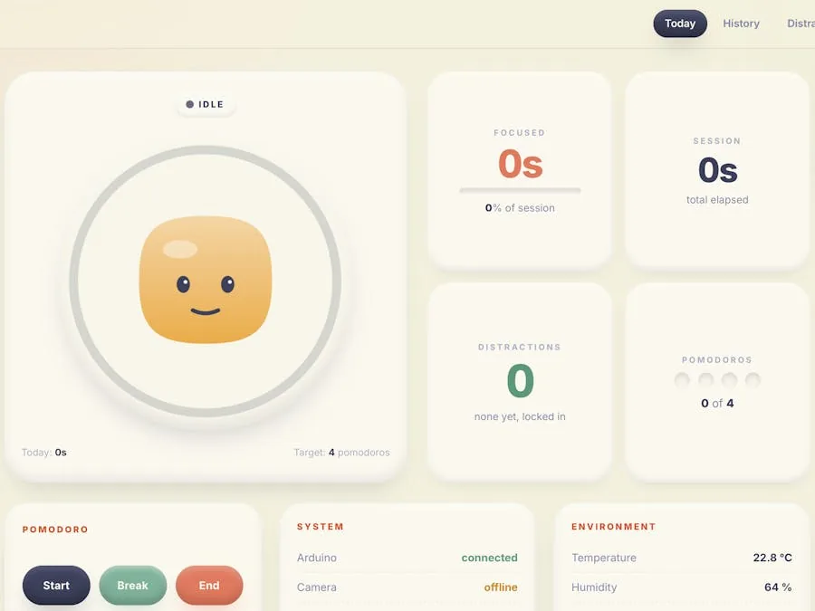
- The dashboard shows it. A Flask page on port 8080 displays the current state, a pomodoro ring, sensor stats, distraction count, and live online/offline pills for the Arduino, camera, and vision service.
The whole loop runs on the Pi as two systemd services and boots automatically on power.
Things used in this project
Hardware
| Component | Qty | Notes |
|---|---|---|
| PIR Motion Sensor (generic) | 1 | Motion detection |
| PTS 645 Series Switch (C&K), a normal push button | 1 | Button input |
| HC-SR04 Ultrasonic Sensor | 1 | Distance to screen |
| Passive piezo buzzer | 1 | Audio feedback |
| LED (generic) | 3 | Red, yellow, green |
| DHT22 Temperature and Humidity Sensor | 1 | Temp + humidity |
| Arduino UNO | 1 | Sensor + actuator controller |
| Raspberry Pi 4 Model B | 1 | Runs the orchestrator and dashboard |
| Spare laptop or phone (camera) | 1 | Anything that can run a tiny web server on your Wi-Fi |
| Photo resistor (LDR) | 1 | Ambient light |
| Breadboard (generic) | 1 | |
| Resistor 220 Ω | 3 | One per LED |
| Resistor 10 kΩ | 1 | Pull-up for the DHT22 data line, plus the LDR voltage divider |
| Jumper wires | 1 pack |
Software
| Tool | Purpose |
|---|---|
| Arduino IDE | Flash the firmware to the Uno |
| Raspberry Pi OS (Raspbian) | OS on the Pi |
| Python 3 | Orchestrator and the Flask dashboard |
| Google Gemini API key | Vision check — focused or not |
Step 1: wire the Arduino
Here is the wiring laid out in Tinkercad so you can see the whole circuit at once.
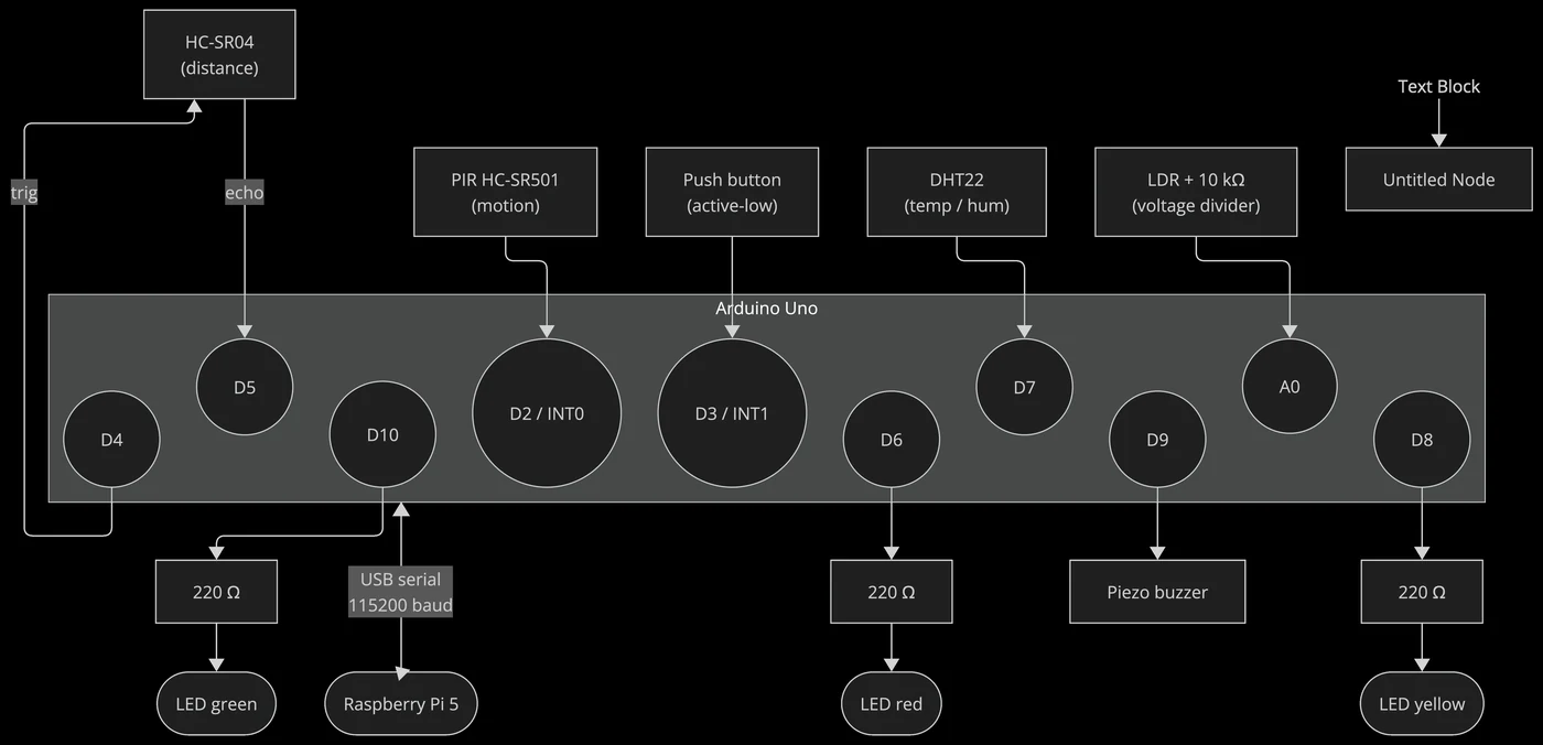
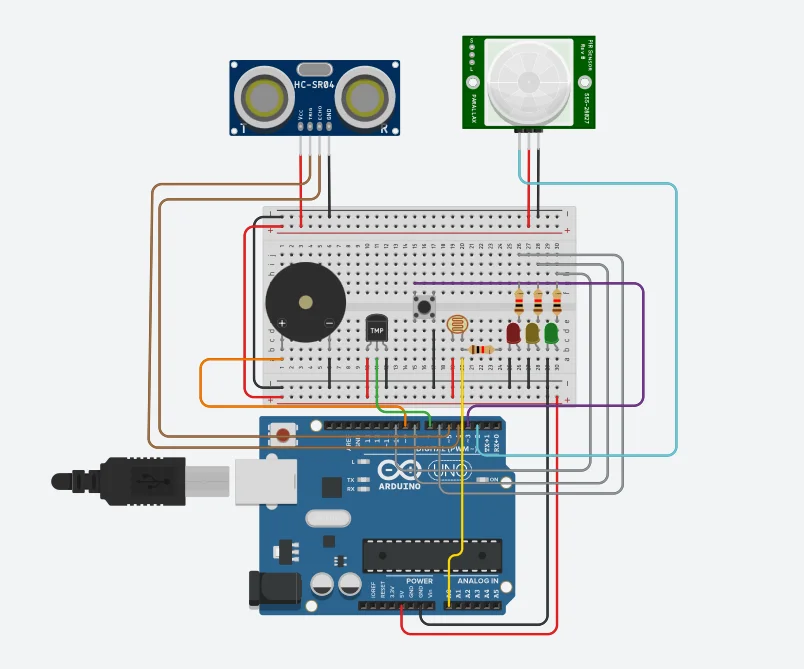
This is the pin map I settled on. It groups inputs at the low-numbered end and outputs at the high end, which keeps the breadboard tidy.
- D2: PIR OUT (
INT0, rising edge interrupt). - D3: Button (
INT1,INPUT_PULLUP, active-low). - D4: HC-SR04 TRIG (10 µs trigger pulse).
- D5: HC-SR04 ECHO (pulse width equals round-trip time).
- D6: LED red (+), 220 Ω to GND.
- D7: DHT22 DATA, with a 10 kΩ pull-up to 5 V.
- D8: LED yellow (+), 220 Ω to GND.
- D9: Buzzer (+), passive piezo, driven by
tone(). - D10: LED green (+), 220 Ω to GND.
- A0: LDR tap (LDR top to 5 V, A0 between the LDR and a 10 kΩ resistor to GND).
- 5 V rail: PIR, HC-SR04, DHT22, LDR top.
- GND rail: everything's ground.
The full ASCII schematic lives in docs/circuit.md.
A few wiring gotchas worth calling out, all of which cost me time on the first attempt:
- The DHT22 needs a 10 kΩ pull-up between DATA and VCC. If you bought the AM2302 breakout module it already has one on board, so do not add a second one.
- The HC-SR04 only works at 5 V. Wire it to a 3.3 V rail and it will quietly return zero echoes with no error to tell you why.
- The button does not need an external resistor. The firmware uses the Arduino's internal pull-up, so just wire D3 to the button to GND.
Before you flash the real firmware, upload arduino/lock_in_demo/lock_in_demo.ino and open the Serial Monitor at 115200 baud. It cycles through every peripheral and prints a status line for each one, so you can confirm the wiring is sane before you put the orchestrator on top. This step saved me twice.
Step 2: flash the real firmware
In the Arduino IDE, install the DHT sensor library by Adafruit (it will pull in Adafruit Unified Sensor automatically). Then open arduino/lock_in_arduino/lock_in_arduino.ino, pick Board: Arduino Uno and the right port, and hit upload.
The firmware does four things on a loop:
1. Streams a 1 Hz JSON sensor frame to the Pi:
{"t":12345,"type":"frame","presence":true,"dist_cm":62.4,
"temp_c":22.1,"hum":54.0,"light":418}
2. Pushes button events the moment they happen, tagged with the gesture (single, double, long):
{"t":12500,"type":"event","event":"button","action":"single"}3. Listens for cmd messages from the Pi to drive the LEDs and buzzer:
{"cmd":"led","state":"FOCUS"}
{"cmd":"buzz","pattern":"confirm"}
4. Runs the buzzer patterns and LED blinking from a non-blocking millis() loop. No delay() calls anywhere except the 10 µs ultrasonic trigger pulse.
One thing worth knowing if you build your own. The button interrupt does almost nothing. It just records which edge fired and the timestamp, then sets a flag. The main loop reads those timestamps, debounces them, and works out whether it was a single, double, or long press. Keeping the slow work out of the interrupt is what stops the button from feeling janky.
The point of keeping the Arduino dumb is that anything timing-sensitive (button debounce, LED blink cadence, buzzer patterns) lives in the microcontroller. The Pi never has to worry about whether its serial write landed on time, and the Arduino never has to worry about anything the Pi is doing. If you are adapting this, that split is the first design choice to copy.
Step 3: set up the Pi
sudo apt update && sudo apt install -y python3-venv python3-pip git
sudo usermod -a -G dialout "$USER"
# log out and back in for the group change to take effect

git clone https://github.com/clupai8o0/lock-in-complete ~/lock-in
cd ~/lock-in/pi
python3 -m venv .venv
source .venv/bin/activate
pip install -r requirements.txt
Now copy pi/.env.example to pi/.env and fill in your Gemini API key and the laptop's LAN IP (next step).
Step 4: run the camera server on a spare laptop
I first planned to use an ESP32-CAM, but in my room it kept dropping frames over Wi-Fi and the JPEGs came back blurry under desk lamps. The simpler answer was a tiny Flask server on a spare laptop that serves a JPEG on GET /capture whenever it is asked. The Pi pulls a frame on its own schedule.
That swap is a good example of the "keep the pieces swappable" idea. The Pi never cared what was on the other end of that URL, so changing the camera was a one-line config change, not a rewrite. If you want to use a phone or an ESP32-CAM instead, you only have to serve a JPEG at one URL.
cd mac_camera
pip install -r requirements.txt
python mac_camera_server.py --port 8081
Find the laptop's IP (ipconfig getifaddr en0 on macOS, hostname -I on Linux). From the Pi, confirm it works:
curl http://<laptop-ip>:8081/capture --output test.jpgSet CAMERA_URL=http://<laptop-ip>:8081/capture in the Pi's .env.
Step 5: run it
cd ~/lock-in/pi
source .venv/bin/activate
./run.sh
run.sh starts both the orchestrator and the Flask dashboard. Open http://<pi-ip>:8080/ in any browser on your LAN. You will see a state badge, a pomodoro ring, four stat cards, and three "system" pills showing Arduino, Camera, and Vision online status.
Sit at the desk and the state goes to IDLE within five seconds. Single-press the button and the state goes to FOCUS, the buzzer plays the confirm pattern, and the session begins. Pick up your phone in front of the camera and the state goes to DEGRADING while the buzzer nags you back.
To make it persistent across reboots, install the two systemd units in pi/systemd/ and enable them. The Pi then becomes a fully autonomous appliance. Power it on and it just works.
How the code is organised
The core of the Pi side is a handful of small Python files, each doing one job. That one rule is what kept the project from sprawling.
pi/
  config.py          # env vars to a dataclass
  database.py        # SQLite schema + queries
  serial_reader.py   # async Arduino bridge, auto-reconnect
  camera_client.py   # async HTTP /capture client
  vision_judge.py    # Gemini call + strict JSON parser
  fsm.py             # the state machine, pure logic
  orchestrator.py    # wires every module into asyncio tasks
  main.py            # entry point
  dashboard/app.py   # Flask, read-only over snapshot.json + SQLite
There is also a small MQTT bus (mqtt_bus.py) and a watchdog helper (sd_notify.py) if you want the dashboard and orchestrator to talk over MQTT and report health to systemd, but you can ignore both to start with.
The single most important design decision is that the state machine is pure logic. No I/O, no threads, no globals, no reading the wall clock inside the logic. The orchestrator pushes events in (on_sensor_frame, on_button, on_vision, tick) and the state machine returns a list of Action records. The orchestrator then turns those actions into side effects.
@dataclass
class Action:
    kind: ActionKind  # SESSION_START, LED, BUZZ, ...
    payload: dict = field(default_factory=dict)
If you are building a similar project, this is the part to copy first, because it is the contract that makes everything else easy to test and reason about. The transitions themselves are simple:
| From | What happens | To |
|---|---|---|
| AWAY | PIR sees someone sit down | IDLE |
| IDLE | single button press | FOCUS (start session, confirm buzzer) |
| FOCUS | vision says you are not focused | DEGRADING (open a distraction, nag buzzer) |
| DEGRADING | vision says you are focused again | FOCUS (close the distraction) |
| FOCUS | the pomodoro timer runs out | BREAK |
| any | PIR sees nobody for a while | AWAY |
Because the logic is pure, you can test the whole thing with a fake clock and no hardware at all. Here is one test that walks a full distraction-then-recovery cycle:
def test_vision_distraction_then_recovery(self):
    self.fsm.on_sensor_frame(self._frame())
    self.clock.advance(6.0); self.fsm.tick()
    self.fsm.on_button("single")
    self.assertEqual(self.fsm.state, State.FOCUS)

    actions = self.fsm.on_vision(VisionInput(False, 0.9, "phone in hand"))
    self.assertEqual(self.fsm.state, State.DEGRADING)
    self.assertIn(ActionKind.DISTRACTION_OPEN, _kinds(actions))

    self.fsm.on_sensor_frame(self._frame())
    self.fsm.on_vision(VisionInput(True, 0.9, "looking at screen"))
    self.clock.advance(70.0)
    self.fsm.on_sensor_frame(self._frame())
    actions = self.fsm.tick()
    self.assertEqual(self.fsm.state, State.FOCUS)
    self.assertIn(ActionKind.DISTRACTION_CLOSE, _kinds(actions))
There are 13 of these. Run them with:
cd pi && python -m unittest test_fsm.pyThe second most important decision is that everything degrades gracefully. A failed Gemini call is one log line and a skipped cycle. An unplugged Arduino is a 5-second reconnect loop while the state machine holds whatever state it was in. A missing camera server is the same idea: vision pauses and the sensor logic keeps running. None of these is an error. They are all designed-for code paths.
Here is what that looks like in the camera client:
try:
    async with self._session.get(self.url) as resp:
        if resp.status != 200:
            self.online = False
            return None
        jpeg = await resp.read()
        ...
        self.online = True
        return CameraCapture(jpeg=jpeg)
except asyncio.TimeoutError:
    self.last_error = "timeout"
    self.online = False
    return None
except aiohttp.ClientError as e:
    self.last_error = f"client error: {e}"
    self.online = False
    return None
No raise, only return None. The orchestrator checks for None and moves on. The dashboard reads the online flag and shows the status to the user. That one convention made the rest of the system simpler to write and reason about.
What you can extend
This setup is small enough to read in one sitting, and it is built so each module can be swapped without touching the others. A few directions if you want to keep going:
- Local vision model. Replace
vision_judge.pywith an Ollama plus Moondream2 version. Same return type, samejudge(jpeg)shape. You would lose the API dependency entirely. - More gestures. The Arduino already decodes single, double, and long press. Adding a quintuple-press for "panic-end-session" is a one-line change in
fsm.on_button. - Habit graphs. The dashboard has a
/historypage and a CSV export but no graphs yet. The data model already records every transition with a timestamp, so a Chart.js view over the last 30 days would be about 20 lines of JavaScript. - Mobile dashboard. It works on a phone but is cramped, since the layout is desktop-first today.
Reflection
Writing this article turned out to be the best debugging tool I had on the whole project. Going through it section by section forced me to re-read every module from a stranger's point of view. I found a handful of dead imports, one near-duplicate JSON call, and a sensor threshold that had been wrong since the second day, and I cleaned all of them up while drafting.
More importantly, explaining why each decision was made surfaced the real lesson. The cleanest fault-tolerant systems are the ones where failure is part of the normal API of every module, not something bolted on at the end. As soon as camera_client.capture() returned None on any error and the orchestrator treated that as a normal code path, the rest of the system got simpler. No exception flows, no "is this thing still alive?" branching, no special cases. That idea, that handling absence is cheaper than handling exceptions, is the thing I will carry into the next embedded project. Producing a teaching case is what made me notice it, so I found the format genuinely useful for my own learning, not just for the marks.
Disclosure
This article is part of an assignment submitted to Deakin University, School of IT, Unit SIT210/730 Embedded Systems Development (Task 10.1D: Project Teaching Case). Repository: github.com/clupai8o0/lock-in-complete.